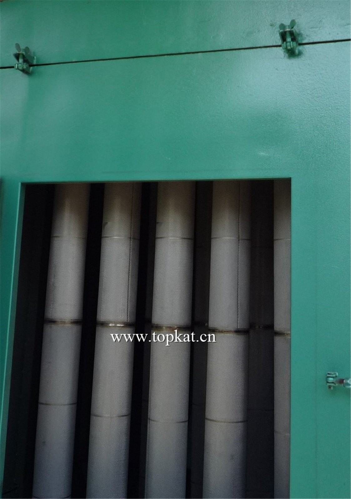
MULCERAFIL All-in-One Ceramic Fiber Filter Tube for Ultra-High Temp
Ceramic Fiber Filter Tubes
Filtration efficiency> 99.9% (typical conditions)
Max. temperature900 °C (continuous & peak)
Dust emission< 2 mg/m³ (typical conditions)
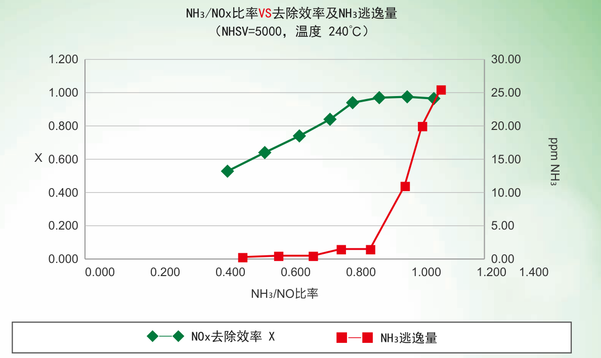
NOx removal> 95% (NH₃/NOx ≈ 1.0, 240 °C, NHSV 5,000)
Dioxin removal95%–99% (200–300 °C)
Product Introduction
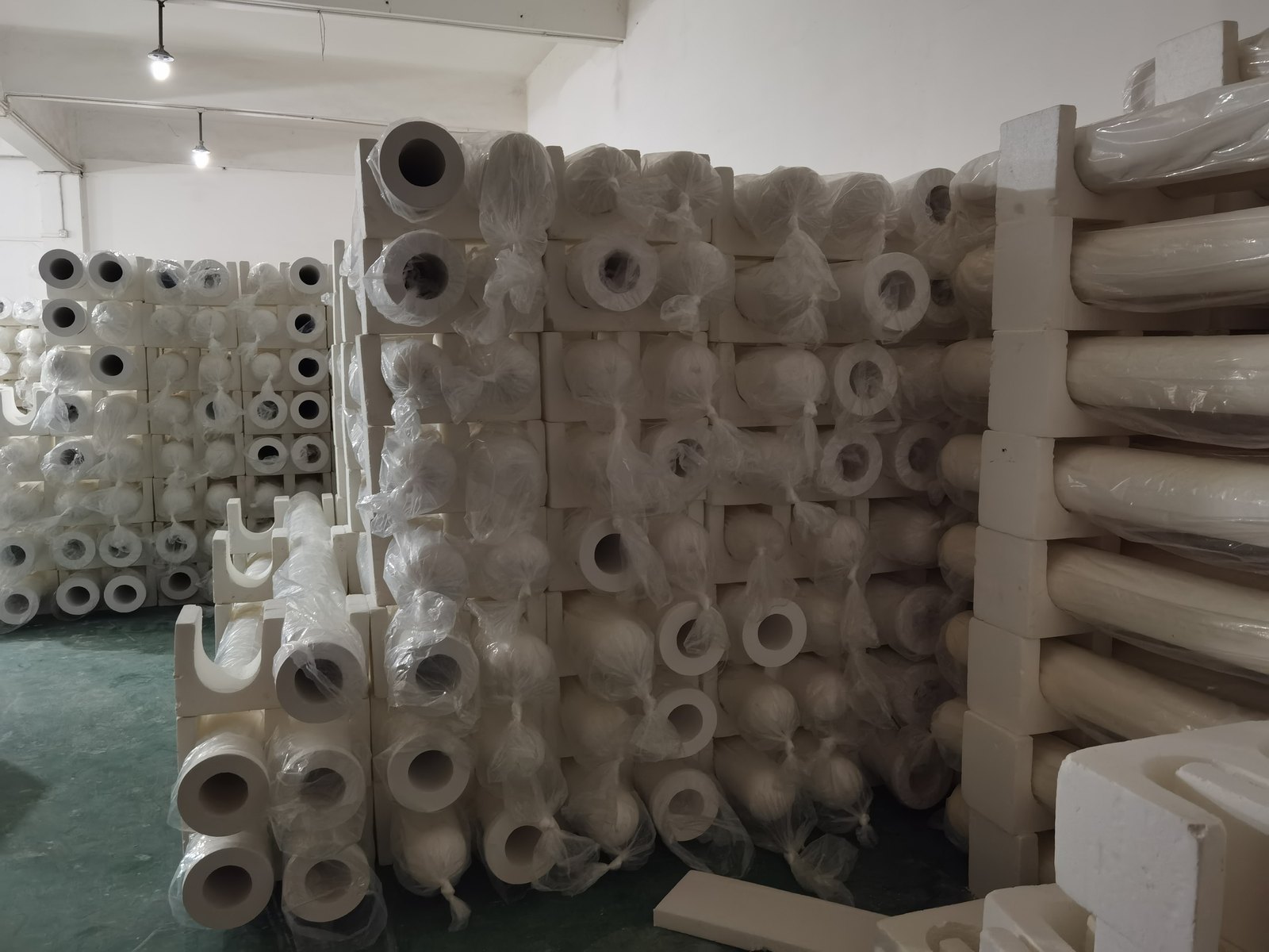
The MULCERAFIL all-in-one catalytic filter element blends a nano-catalyst into the inorganic fibre granules so that the catalyst is distributed evenly through the filter wall. While filtering dust at high efficiency, it simultaneously removes dioxins, NOx, VOC and acid gases, handling gaseous pollutants and dust in one step inside a single element.
MULCERAFIL All-in-One Catalytic Filter Element — Dedusting, DeNOx and Dioxin Removal in One Step
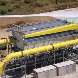
The MULCERAFIL all-in-one catalytic filter element, made by AIFILTECH (Guangzhou Tuokai Environmental Technology Co., Ltd.), is formed from inorganic fibre granules blended with a nano-catalyst, the catalyst being distributed evenly through the filter wall. It keeps the high-temperature dedusting performance of a ceramic fibre element and at the same time removes NOx, VOC, dioxins and acid gases. Dedusting, desulphurisation, DeNOx, deacidification, dioxin and VOC removal are combined into a single step inside one element. Typical duties include waste incineration, secondary aluminium, electric furnaces and glass furnaces where several pollutants have to be handled together.
<2 mg/m³Dust
>95%HCl removal
>80%SO₂ removal
>95%NOx removal
>99%VOC removal
>99%Dioxin removal
Figures are measured results for the one-step process under typical conditions. Actual performance varies with gas composition, temperature, NH₃/NOx ratio and NHSV.
How the catalytic element differs from the standard ceramic fibre element
Table 1 — MULCERAFIL all-in-one catalytic element versus ceramic fibre element
Item
Ceramic fibre element
All-in-one catalytic element
Main function
High-temperature dedusting
High-temperature dedusting plus catalytic removal of gaseous pollutants
Pollutants handled
Dust (particulate)
Dust, NOx, VOC, dioxins, SO₂, HCl and other acid gases
Media composition
Bonded inorganic fibre granules
Inorganic fibre granules plus nano-catalyst
Temperature rating
900 °C
900 °C
Dimensions
Identical — interchangeable on the same tubesheet
Structure and catalytic mechanism
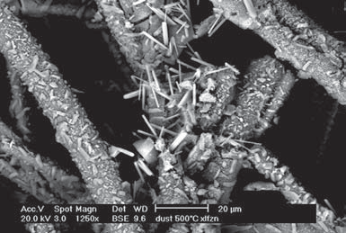
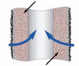
The nano-catalyst is distributed evenly through the whole filter wall. With a wall thickness of 10–20 mm, the gas stays in contact with the catalyst long enough to give a high utilisation rate. As the gas passes through the wall, NOx, VOC and dioxins are broken down into harmless components over the catalyst.
SEM image of the catalytic filter elementWall thickness 10–20 mm; catalyst distributed across the full section
What the structure means in practice
Catalyst throughout the wall; the 10–20 mm thickness provides long gas–catalyst contact time
On comparable duties, catalytic efficiency is 5–15% higher than with a conventional SCR process
Avoids the efficiency losses caused by gas turbulence in SCR reactors
Catalyst is distributed through the wall, so catalytic performance stays stable in service
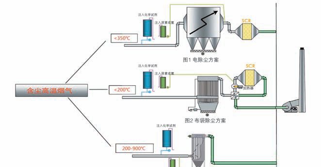
No separate SCR reactor is needed, which shortens the gas-cleaning process
Smaller footprint and correspondingly lower overall investment
The one-step process
Dust, HCl, SOx, NOx, VOC, dioxins Raw mixed pollutant gas
→
MULCERAFIL catalytic element NaHCO₃ (or Ca(OH)₂) + NH₃ (ammonia or urea) injected
→
Clean discharge Multiple pollutants removed inside a single element
Measured removal performance in a single step
<2 mg/m³Dust
>95%HCl
>80%SO₂
>95%NOx
>99%VOC
>99%Dioxins
Typical applications
1. High-temperature desulphurisation, DeNOx and dedusting in one step
For boilers, kilns, sintering machines, power plants and cement plants. At an NH₃/NOx ratio near 1.0, 240 °C and NHSV 5,000, NOx removal reaches more than 95% while ammonia slip stays low.
NH₃/NOx ratio versus removal efficiency and NH₃ slip (NHSV 5,000; 240 °C)One-step DeNOx and dedusting: the catalyst is integrated into the element, so no separate SCR reactor is required
2. Dioxins, VOC, deacidification and dedusting combined
For waste incineration, secondary aluminium, electric furnaces, and sulphuric and nitric acid plants. Conventional dioxin control usually captures dioxins and VOC from the gas phase and holds them on a solid sorbent; the pollutants themselves are not destroyed. The nano-catalyst in the MULCERAFIL element breaks dioxins and VOC down into harmless components, without a separate unit for the purpose.
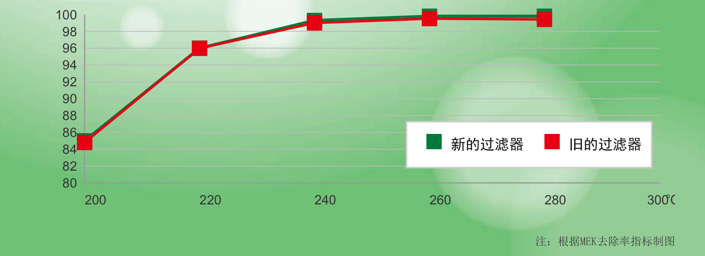
Across the 200–300 °C range, both new elements and elements that have been in service for a long time hold dioxin removal (measured as MEK removal) at 95–99% and above.
Dioxin removal efficiency — plotted against MEK removal
Applications
Table 2 — Industries and typical duties for the all-in-one catalytic element
Industry
Notes
Waste incineration
Flue gas from industrial, chemical, municipal, hazardous and medical waste incinerators, with emphasis on dioxins, VOC and acid gases
Dioxin emission of 0.00032 ng-TEQ/Nm³, below the EU limit of 0.1 ng-TEQ/Nm³.
Standard specifications
Table 5 — Standard sizes for MULCERAFIL all-in-one catalytic filter elements
Overall length (mm)
Outside diameter (mm)
Flange height (mm)
Flange diameter (mm)
Filter area (m²)
1000
60
20
80
0.19
1250
60
20
80
0.23
1500
60
20
80
0.28
1800
150
30
195
0.83
2000
123
15
159
0.77
2045
130
30
160
0.82
2250
150
30
195
1.05
3000
125
30
160
1.17
3000
150
30
195
1.40
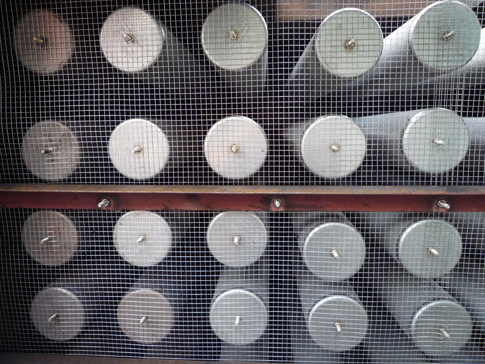
Sizes above are standard. Flange type and dimensions can be made to suit an existing tubesheet. Catalytic and ceramic fibre elements share the same dimensions and are directly interchangeable.
Frequently asked questions
How does the all-in-one catalytic element differ from a standard ceramic fibre element?
A standard ceramic fibre element handles high-temperature dedusting. The catalytic element blends a nano-catalyst into the inorganic fibre granules, distributed evenly through the wall, so it removes NOx, VOC, dioxins and acid gases at the same time as it filters dust.
What temperature can the catalytic element handle?
The MULCERAFIL all-in-one catalytic element is rated to 900 °C continuous and peak, the same as the ceramic fibre element. Dioxin and VOC removal is normally carried out in the 200–300 °C range.
Does catalytic efficiency fall over time?
The catalyst is distributed through the full 10–20 mm wall thickness, and performance stays stable in service. Because the gas flows through the wall in a stable pattern, the efficiency losses associated with turbulence in conventional SCR reactors are avoided.
How does this compare with a separate SCR reactor?
The catalyst is integrated into the element, so dedusting and DeNOx happen in the same vessel. No separate SCR reactor or associated ductwork is needed, the process is shorter and the footprint is smaller. On comparable duties, catalytic efficiency is 5–15% higher than with a conventional SCR process.
Are dioxins adsorbed or destroyed?
They are destroyed. Conventional routes typically capture dioxins and VOC from the gas phase and hold them on a solid sorbent, leaving the pollutants intact. The nano-catalyst in the MULCERAFIL element breaks dioxins and VOC down into harmless components.
Which industries can use it?
Waste incineration including hazardous and medical waste, metallurgy (calcium carbide, ferroalloy, primary and secondary aluminium, sintering machines, blast furnace and converter), glass, ceramics, cement, power generation, coal gasification and precious metal recovery.
All data above are obtained under specific test conditions; the actual solution must be engineered to site conditions. AIFILTECH provides custom design and sizing based on actual gas volume, temperature, dust characteristics and emission limits.