The MULCERAFIL ceramic fibre filter element is a low-density, porous, tube-shaped filter formed from bonded inorganic fibre granules. Lightweight yet rigid, it needs no supporting cage and withstands 900 °C continuously and at peak, allowing hot flue gas to be filtered directly without cooling while capturing dust below 1 micron. It is used in waste incineration, metallurgy, glass, cement and chemical plants.
MULCERAFIL Ceramic Fibre Filter Element — Rated to 900 °C for Ultra-High-Temperature Flue Gas
The MULCERAFIL ceramic fibre filter element is an ultra-high-temperature filtration element made by AIFILTECH (Guangzhou Tuokai Environmental Technology Co., Ltd.). Produced from bonded inorganic fibre granules, it is a low-density, porous, tube-shaped filter. Lightweight yet rigid, it requires no supporting cage and operates continuously — and at peak — at up to 900 °C. It filters hot flue gas directly, without pre-cooling, and captures dust below one micron. Typical applications include waste incineration, metallurgy, glass, cement and chemical processing.
900 °CContinuous / peak rating
>99.9%Filtration efficiency
<2 mg/m³Outlet dust concentration
10+ yearsService life in reference projects
What is a ceramic fibre filter element?
A ceramic fibre filter element is a rigid inorganic filter made from inorganic fibres and binder granules that are blended, formed and fired into a test-tube-shaped cartridge. Unlike a flexible fabric bag, it does not rely on a textile structure to hold its shape, so it withstands both the filtration pressure drop and the mechanical shock of pulse-jet cleaning without a support cage.
The MULCERAFIL element has a porous, open structure with high porosity and good gas permeability, so gas passes through the filter wall at low resistance. Dust is retained on the outer surface, forming a dust cake that the pulse-cleaning system removes at set intervals. The element resists strong acids and alkalis, will not burn, and can be used on gas streams containing flammable or explosive components.
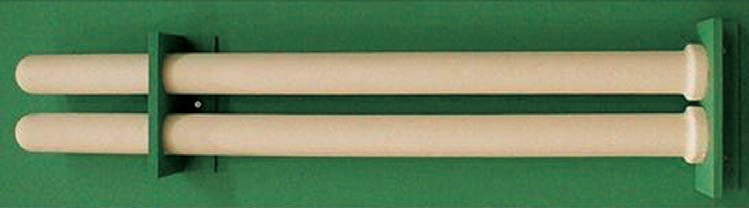
MULCERAFIL ceramic fibre filter element (rigid, cage-free design)
How it works
Filtration
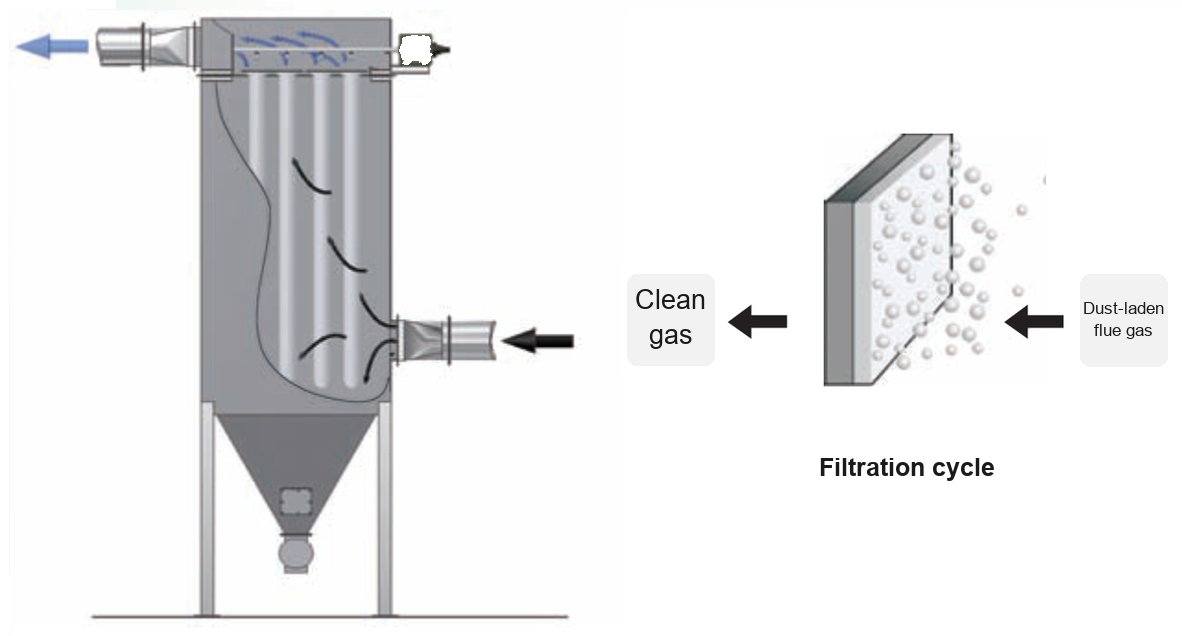
Elements are fixed to the tubesheet in the upper part of the housing. Dust-laden hot gas enters the dirty-air plenum and is drawn from outside to inside through the filter wall. Dust is retained on the outer surface while clean gas passes through the wall into the clean-air plenum above the flange, from where it goes to downstream equipment or to the stack.
Dust-laden gas passes from outside to inside; dust is retained on the outer surface
Pulse-jet cleaning
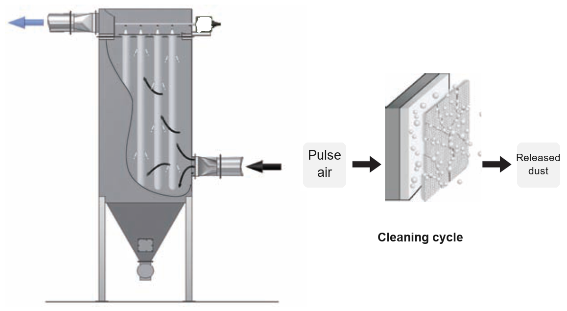
As the dust cake thickens, the differential pressure across the element rises. When it reaches the set point, cleaning starts automatically: a pressure sensor or timer triggers the pilot valve, which opens the diaphragm valve and releases a short pulse of compressed air into the element inlet. The instantaneous reverse flow dislodges the dust cake, which falls into the hopper, and the element returns to filtration.
Pulse-jet cleaning: the dust cake is released and falls into the hopper
Performance and features
Rated to 900 °C continuous and peak; non-combustible
Resistant to strong acids and alkalis
Long service life — reference installations have run for more than 10 years
Fine filtration — captures dust particles below 1 micron
High strength and abrasion resistance; low operating pressure drop
Stable operation at a filtration velocity of 3 m/min
Operates under high pressure without damage
Rigid, cage-free construction allows a compact, simple collector layout
Figures above are drawn from product documentation and measurements on operating installations. Actual performance varies with gas composition, temperature, dust loading and other site conditions, so each selection should be engineered against the specific duty.
Temperature rating compared with common baghouse media
Table 1 — Temperature rating: MULCERAFIL ceramic fibre element versus common filter media
Filter media
Continuous (°C)
Peak (°C)
Polyester
140
160
Nomex
200
240
P84
240
260
PTFE (Teflon)
260
280
Glass fibre
260
300
MULCERAFIL ceramic fibre element
900
900
The values above are the nominal ranges normally quoted for each media type. Because the ceramic fibre element works directly in gas above 500 °C, systems built around it generally do not need a gas-cooling stage.
System comparison: high-temperature filtration versus conventional baghouse
Basis: 10,000 Am³/h of raw gas at 500 °C. A fabric filter would first require cooling to around 200 °C, using either a heat-exchange system or dilution air.
Table 2 — MULCERAFIL high-temperature system versus conventional baghouse configurations (example duty)
Configuration
Cooling method
Cooler power (kW)
Added gas volume (m³/h)
Filtration velocity (m/min)
Filter area (m²)
Collector size (relative)
Installed power (kW)
MULCERAFIL high-temperature system
Not required
None
None
3
56
1
15
Conventional baghouse
Water cooling (heat exchanger, cooling tower, pumps)
6.5
None
1
84
1.5
14
Conventional baghouse
Air cooling (heat exchanger, fan)
5.5
None
1
84
1.5
13
Conventional baghouse
Dilution air
None
17,000
1
450
8
55
What the comparison shows: on this duty, a system built on MULCERAFIL elements needs no cooler, cooling tower, pumps, heat exchanger or dilution-air fan. Filter area and collector size are smaller than in the fabric-filter options, and both capital cost and operating energy fall accordingly. The dilution-air route increases gas volume substantially, which pushes up both plant size and installed power.
Applications
Table 3 — Industries and typical duties for ceramic fibre filter elements
Industry
Notes
Waste incineration
Flue gas from industrial, chemical, municipal, hazardous and medical waste incinerators
Metallurgy
Ferrous and non-ferrous processing: calcium carbide, ferroalloy, primary and secondary aluminium, alumina calcining, sintering machines, copper smelting, blast furnace, converter
Glass
High-temperature dedusting of glass furnace flue gas
Ceramics
Flue gas treatment for ceramic kilns
Cement
High-temperature gas cleaning for cement kilns and sintering machines
Power generation
High-temperature dedusting of boiler flue gas
Chemical processing
Coal gasification and high-temperature precision filtration of process gas
Precious metal recovery
High-temperature gas cleaning in precious metal smelting and recovery
Installation
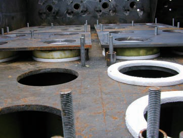
The MULCERAFIL ceramic fibre element and the all-in-one catalytic element install the same way, in four steps:
Place the gasket on top of the tubesheet hole
Lower the element vertically into the tubesheet hole
Align the hold-down with the tubesheet studs and seat it on the element flange
Tighten the nuts so the hold-down clamps the element in place
Gasket in place / element lowered into the tubesheetHold-down secured / nuts tightened
The element is rigid enough to serve without a cage. Removal follows the same steps in reverse and can be handled by one person.
Standard specifications
Table 4 — Standard sizes for MULCERAFIL ceramic fibre filter elements
Overall length (mm)
Outside diameter (mm)
Flange height (mm)
Flange diameter (mm)
Filter area (m²)
1000
60
20
80
0.19
1250
60
20
80
0.23
1500
60
20
80
0.28
1800
150
30
195
0.83
2000
123
15
159
0.77
2045
130
30
160
0.82
2250
150
30
195
1.05
3000
125
30
160
1.17
3000
150
30
195
1.40
Sizes above are standard. Flange type and dimensions can be made to suit an existing tubesheet. Ceramic fibre and catalytic elements share the same dimensions and are directly interchangeable.
Frequently asked questions
What temperature can the ceramic fibre filter element handle?
The MULCERAFIL ceramic fibre element is rated to 900 °C both continuously and at peak. For comparison, common baghouse media are rated around 140 °C for polyester, 260 °C for PTFE and 300 °C for glass fibre.
Does the element need a support cage?
No. The element is a rigid inorganic structure with enough strength to withstand the filtration pressure drop and pulse cleaning. Installation requires only a gasket, the tubesheet hole and a hold-down.
How does a ceramic fibre element differ from a metal filter bag?
Both serve as high-temperature filtration elements. The ceramic fibre element is a rigid, non-metallic inorganic cartridge rated to 900 °C with strong resistance to acids and alkalis. A metal filter bag uses metal fibre or felt media and offers advantages in mechanical shock resistance and cleanability. Selection depends on gas temperature, composition, dust loading and cleaning method.
What filtration efficiency can be expected?
Under typical conditions the MULCERAFIL element achieves filtration efficiency above 99.9% with outlet concentrations below 2 mg/m³, capturing dust below one micron. Actual results depend on particle size distribution, filtration velocity and cleaning intervals.
Does the gas have to be cooled before filtration?
No. The element filters directly at temperatures up to 900 °C, so systems using it generally need no cooler, cooling tower or dilution-air fan, and both filter area and plant size can be reduced accordingly.
How long does the element last?
Reference installations have run for more than ten years. Service life in practice depends on corrosive components in the gas, temperature swings, cleaning frequency and maintenance.
All data above are obtained under specific test conditions; the actual solution must be engineered to site conditions. AIFILTECH provides custom design and sizing based on actual gas volume, temperature, dust characteristics and emission limits.