
Platinum or Iridium? Coating Processes for Titanium Porous Transport Layers
Ask any PEM electrolyzer engineer about porous transport layers and the conversation reaches coatings within minutes. Titanium felt and porous titanium plates are the standard anode-side (and sometimes cathode-side) porous transport layers, but bare titanium hides a problem behind an apparently passive surface: a thin, insulating oxide skin that grows under heat and potential, pushing interfacial contact resistance upward over thousands of operating hours. A fraction of a micrometer of platinum — or iridium, depending on which side of the cell you are building — keeps that interface conductive for the life of the stack.
This guide walks through the four industrial coating routes, compares them on the axes that actually matter (interior coverage of a sintered felt, adhesion, cost, throughput), explains where platinum ends and iridium begins, and closes with the acceptance checks we consider non-negotiable on incoming material.
The porous conductive layer between the bipolar plate and the catalyst layer. It distributes water to the reaction sites, drains product gas, and carries current across the interface. In PEM stacks it is typically sintered titanium fiber felt or sintered porous titanium plate.
A thin noble-metal layer (industrially 0.2–0.5 μm on PTLs) that stabilizes the Ti/catalyst interface: it lowers and holds contact resistance, and on hydrogen-side surfaces it suppresses titanium hydriding. It is not primarily a catalyst layer.
An iridium metal or iridium-oxide layer intended for oxygen-evolving (high-potential) environments. IrO₂ tolerates the anodic potential window where platinum progressively oxidizes and dissolves. It is usually specified as a loading (mg/cm²) rather than a thickness.
The mass of precious-group metal per unit area (mg/cm²). Coatings below a few micrometers are easier to compare — and to purchase against — by loading than by geometric thickness.
Why bare titanium eventually fails the interface
Sintered titanium arrives with an oxide skin a few nanometers thick. Under stack conditions — temperature, potential, time — that skin thickens. Titanium oxide is a wide-bandgap insulator, so every extra nanometer sits directly in the current path between bipolar plate and catalyst layer. The visible symptoms are slow ones: interface resistance that drifts upward over months of operation, local hot spots at under-compressed spots, and on the cathode side, titanium hydride formation that embrittles fiber surfaces. A precious-metal coating separates titanium from the reaction environment and pins the interface resistance near its initial value.
Four coating routes, one pre-treatment chain
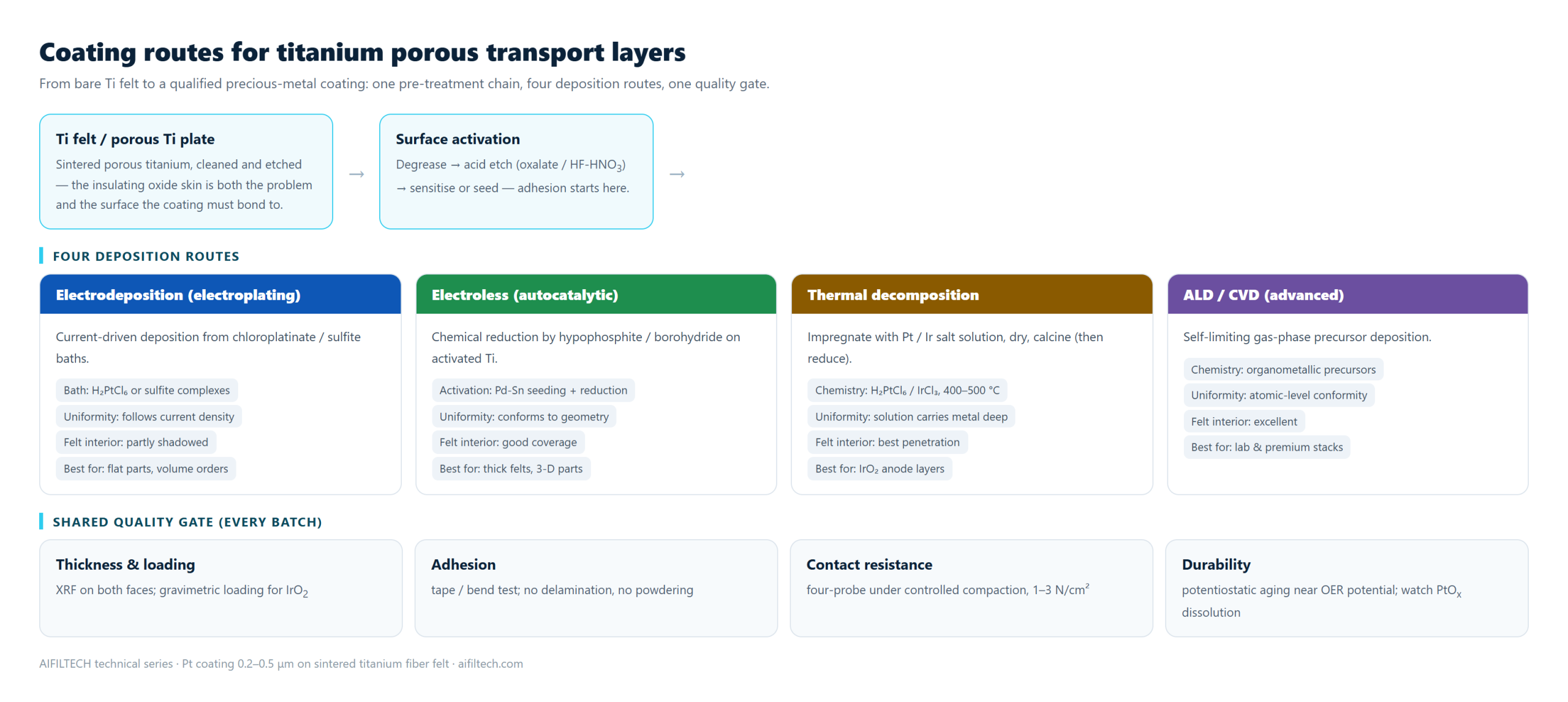
Every industrial route starts from the same chain: degrease, acid etch (oxalate or HF-HNO₃ mixtures) to strip and roughen the native oxide, then sensitize or seed the surface. Adhesion is decided here, not in the plating bath. The four routes then differ in how they deliver metal onto — and into — the felt:
- Electrodeposition (electroplating). Current-driven deposition from chloroplatinate or sulfite baths. Mature, fast, and economical at volume, but deposition follows current density: interior fibers of a thick felt receive less current than the surface, so interior coverage is partial.
- Electroless (autocatalytic) plating. Palladium-tin activation followed by chemical reduction (hypophosphite or borohydride systems). No current distribution to fight, so the coating conforms to complex geometry and penetrates felt interiors well. Costs more per bath and demands tight chemistry control.
- Thermal decomposition. Impregnate with Pt or Ir salt solution, dry, calcine at 400–500 °C (often followed by a reduction step). The solution carries metal deep into the pore network — the best interior penetration of the four — and it is the natural route for IrO₂ anode layers. Coatings come out as fine oxide/particulate films rather than dense metal.
- ALD / CVD (advanced). Self-limiting gas-phase deposition with atomic-level conformity, including deep pores. Performance is outstanding; throughput and equipment cost confine it to premium and laboratory stacks today.
The comparison that decides your purchase order
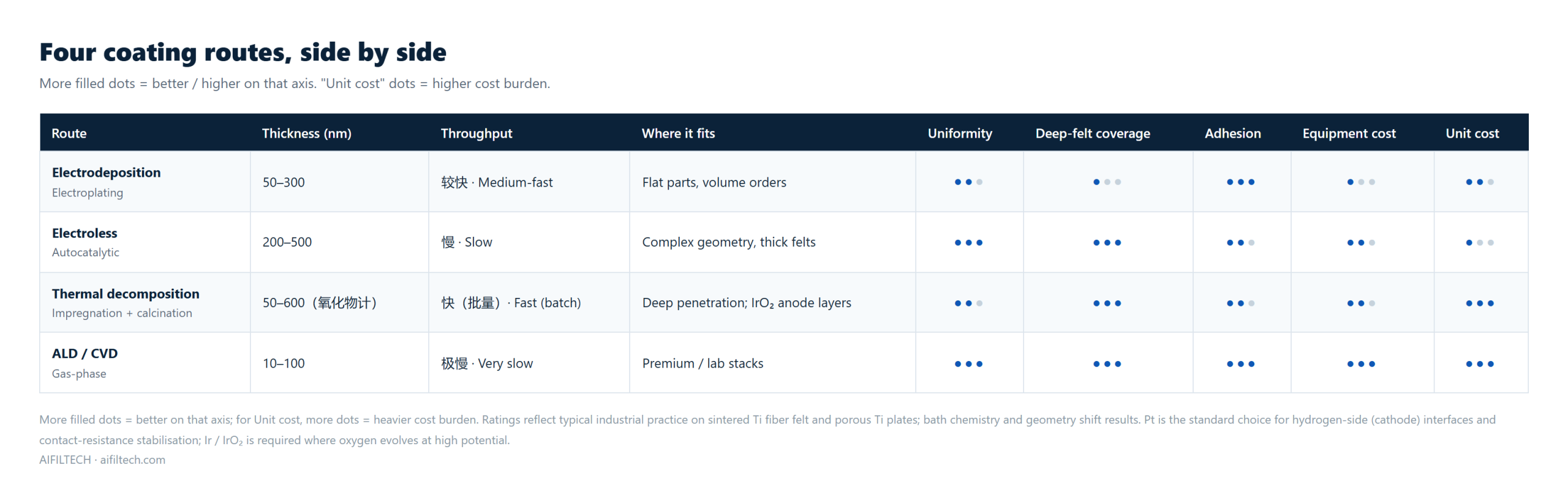
| Route | Typical thickness | Felt interior coverage | Uniformity control | Relative cost | Where it fits |
|---|---|---|---|---|---|
| Electrodeposition | 50–300 nm | Partial (current shading) | Via current distribution / anode design | Low–medium | Flat sheets, volume orders |
| Electroless | 200–500 nm | Good | Bath chemistry and time | Medium | Thick felts, 3-D parts |
| Thermal decomposition | 50–600 nm (often as oxide) | Best | Solution concentration, impregnation cycles | Medium | Deep penetration, IrO₂ anode layers |
| ALD / CVD | 10–100 nm | Excellent | Precursor dosing cycles | High | Premium / lab stacks |
Anode or cathode: where platinum ends and iridium begins
The coating decision follows the electrode side, not the vendor catalogue:
| Position | Environment | Coating of choice | Rationale |
|---|---|---|---|
| PEM cathode (hydrogen evolution) | Reducing, low potential | Pt, 0.2–0.5 μm | Pt is stable at HER potentials; it stabilizes contact resistance and suppresses Ti hydriding on hydrogen-side surfaces |
| PEM anode (oxygen evolution) | Strongly oxidizing, >1.6–1.8 V vs RHE | Ir / IrO₂ | Pt progressively oxidizes (PtOₐ) and dissolves at OER potentials; IrO₂ tolerates the same window |
| Alkaline / AEM stacks | Concentrated KOH or alkaline feed | Usually none | Nickel felt and mesh perform the same role at far lower cost; coatings rarely justified |
A common design pattern in commercial PEM stacks: Ir-coated (or IrO₂-coated) titanium PTL at the anode, platinum-coated titanium PTL — or a carbon-based cathode layer — at the cathode. Specifying the two sides independently also avoids paying for iridium where platinum suffices, which matters: iridium is scarcer and priced accordingly.
How thick, and specified how?
- Platinum: 0.2–0.5 μm is the industrial mainstream. The coating stabilizes an interface; it is not a catalyst layer, and pushing beyond that range raises cost without proportional benefit. Specify by XRF-measured thickness on both faces, plus a loading figure.
- Iridium: usually specified as loading, commonly in the 0.1–0.5 mg/cm² range on PTLs, with the coating present as Ir metal or IrO₂ depending on the route. Confirm which phase your catalyst-coating supplier expects, because the bonding interface differs.
- Uniformity beats thickness: a 0.3 μm coating with even interior coverage outlives a 1 μm surface-only deposit, because failure initiates where the coating is thinnest — inside the felt.
Acceptance checks that keep a coating alive
- Thickness & loading: XRF on both faces at several points; gravimetric loading for oxide-type IrO₂ layers.
- Adhesion: tape test or bend test — no delamination, no powdering. Poor adhesion shows up first as particle shedding that contaminates the membrane.
- Contact resistance: four-probe measurement under controlled compaction (1–3 N/cm²), compared against the uncoated baseline.
- Durability screen: potentiostatic aging near the operating potential for the relevant side; watch for potential drift that signals dissolution (especially PtOₐ formation at anodic potentials).
- Microstructure: SEM/EDS on a cross-section for batch qualification — confirms coverage inside the pore network, not just on the plane surface.
Five mistakes that cost stacks months of life
- Specifying platinum on the anode side because it is cheaper than iridium — then replacing the PTL after PtOₐ dissolution drives interface resistance up.
- Ordering “thicker = safer” coatings; beyond the working range, thickness buys cost, not life.
- Judging coverage by the surface appearance of a felt; the interior fibers are where under-coating hides.
- Skipping the adhesion test because the coupon “looked fine” — particle shedding does its damage weeks later inside the cell.
- Leaving felt thickness tolerance out of the coating specification; compaction and contact resistance calculations assume the delivered thickness range, not the nominal one.
Related guides
For the surrounding context: nickel felt vs titanium felt covers the base-metal decision, electrolyzer stack structure shows where the PTL sits in the repeat unit, the material selection guide turns this into a supplier-facing checklist, and the titanium fiber felt product page lists the coated-felt specifications we supply.
Sourcing coated titanium porous transport layers?
AIFILTECH sinter-manufactures titanium fiber felt and porous titanium plates, with platinum coating (0.2–0.5 μm) available as a standard option; other noble-metal coatings are reviewed case by case against your operating window.
- Send us: stack type, electrode side (anode / cathode), operating potential and current density, felt thickness and porosity, coating specification and annual volume.
- You get: a coating-specification confirmation within one business day, sample sheets with XRF and contact-resistance data, and consistent batch records.