
ALK, PEM, AEM and SOEC: Water Electrolysis Routes Compared
Every water electrolysis project eventually hits the same fork: alkaline (ALK), proton exchange membrane (PEM), anion exchange membrane (AEM), or solid oxide (SOEC). The four routes are often presented as competing philosophies, but for a materials buyer the question is narrower and more practical: which chemistry will the inside of my stack see, and therefore which porous metal layers, separators and coatings will survive it?
This guide defines each route, compares them on the parameters that actually move a project, and maps the porous metal materials each one consumes. A companion guide covers the layer-by-layer structure of an electrolyzer stack in detail.
Definitions first: what each acronym means
The classical route: two electrodes separated by a porous diaphragm, immersed in a circulating 20–30% KOH (or NaOH) solution. Water is reduced at the cathode, hydroxide ions carry the charge through the liquid electrolyte. Electrodes and most internal components are nickel-based because nickel resists caustic solution. Operating temperature is typically 60–90 °C at current densities of roughly 0.2–0.5 A/cm².
A solid polymer membrane (perfluorosulfonic acid, PFSA family) conducts protons from anode to cathode. The environment is strongly acidic, so the anode side is built from titanium: Ti felt or sintered porous Ti plates as the porous transport layer (PTL), titanium bipolar plates, and iridium-based catalysts where oxygen evolves. Operating temperature is typically 50–80 °C, with current densities from 1 A/cm² up to 3 A/cm² in advanced designs.
A hybrid: a solid anion-conducting membrane like PEM, but an alkaline chemistry like classical electrolysis. Because the environment is caustic rather than acidic, nickel- and iron-based catalysts can replace platinum-group metals, and nickel felt or mesh serves as the porous transport layer. AEM is the youngest of the four routes; membrane lifetime and megawatt-scale operating hours are still being proven, which is the main engineering risk, not the lab current density.
Runs hot: 700–850 °C, with a ceramic oxygen-conducting electrolyte (yttria-stabilized zirconia family) and steam rather than liquid water. Electricity consumption per Nm³ is the lowest of the four because a large share of the energy comes as heat, which makes it attractive where waste heat exists. Ceramics, seals and long-term degradation are the engineering bottlenecks; the porous-metal content is comparatively small.
The comparison that matters
Ranges below are typical published figures for commercially oriented systems. Real projects vary with current density, water quality, and where you draw the system boundary (stack only, or stack plus power electronics and gas treatment).
| Parameter | ALK | PEM | AEM | SOEC |
|---|---|---|---|---|
| Electrolyte | 20–30% KOH liquid | Solid PFSA membrane (acidic) | Solid AEM membrane (alkaline) | Ceramic (YSZ family) |
| Gas separator | Porous diaphragm (ZrO&sub2; on PPS) | The membrane itself | The membrane itself | The electrolyte itself |
| Anode catalyst | Ni-based (Raney Ni, NiFe) | IrO&sub2; (iridium is the scarcity problem) | Ni–Fe / Ni–Co (PGM-free possible) | Perovskite oxides |
| Anode porous layer | Ni mesh / Ni foam / Ni felt | Ti felt or porous Ti plate | Ni felt (Ti felt on some designs) | Ceramic electrodes |
| Operating temperature | 60–90 °C | 50–80 °C | 40–60 °C | 700–850 °C |
| Typical current density | 0.2–0.5 A/cm² | 1–3 A/cm² | 0.3–1.5 A/cm² | 0.3–1.0 A/cm² |
| Electricity, system level | ~4.3–5.0 kWh/Nm³ | ~4.2–4.8 kWh/Nm³ | ~4.4–5.0 kWh/Nm³ | ~3.0–3.6 kWh/Nm³ (with heat) |
| Load flexibility | Slow ramp; gas crossover limits minimum load | Fast ramp; suits wind/solar pairing | Potentially fast; limited operating data | Best with steady heat supply |
| Industrial maturity | Decades, multi-hundred-MW references | Megawatt-scale, growing fast | Pilot to small MW | Demonstration scale |
| Main cost driver | Steel, nickel, diaphragm | Iridium, titanium, membrane | Membrane lifetime × replacement | Cell manufacturing and seals |
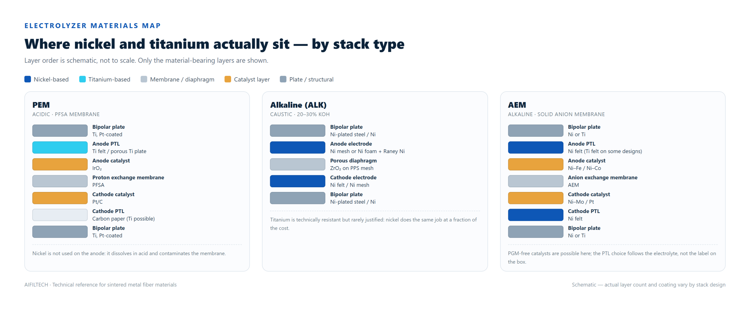
Which porous metals each route consumes
This is where a materials supplier sees the four routes differently from a technology vendor:
- ALK is a nickel project: nickel mesh as current collector and electrode support, nickel foam or Raney-type coatings as the catalytic electrode body, nickel-plated steel bipolar plates, and a ZrO&sub2;-coated PPS diaphragm. Titanium appears rarely, and usually only in peripheral equipment.
- PEM is a titanium project on the anode: Ti felt or porous Ti plates as PTL (0.2–1.0 mm, 50–70% porosity in common commercial specs, often with a 0.2–0.5 μm Pt coating), titanium bipolar plates, and carbon-based layers on the cathode. The iridium inventory is a supply-chain question, but the titanium PTL is a manufacturing one.
- AEM is mostly a nickel project with a solid membrane: Ni felt PTLs on both sides in many published designs, Ti felt where a design wants higher corrosion margin at the anode, and Ni–Fe or Ni–Co catalysts.
- SOEC needs little porous metal inside the cell; interconnects and balance-of-plant dominate.
How projects actually choose
- Pair the electrolyzer with the power profile. Wind and solar with heavy fluctuation favor PEM’s fast ramping; a steady baseload or a cheap night tariff makes ALK’s slower dynamics acceptable; SOEC wants a stable heat source.
- Count the scarce metals. Iridium loading is the structural constraint on multi-gigawatt PEM build-outs; AEM and ALK avoid it. This is a procurement risk question, not just a chemistry question.
- Match maturity to the financing. Banks and EPCs price risk by operating hours. ALK has decades of references; PEM has fast-growing megawatt references; AEM and SOEC are still building theirs, which shows up in warranty terms.
- Check what the water and the site allow. PEM demands high-purity water; ALK tolerates more but manages caustic circulation; SOEC needs steam raising.
Frequently asked
What is the difference between PEM and alkaline water electrolysis?
PEM conducts protons through a solid acidic membrane and therefore needs titanium hardware and iridium catalysts; alkaline conducts hydroxide through liquid KOH with a porous diaphragm and nickel hardware. PEM ramps faster and runs at higher current density; alkaline is cheaper to build and has the longest operating record.
Is AEM just a cheap version of PEM?
No. AEM keeps the solid-membrane architecture but runs alkaline, which allows PGM-free nickel-iron catalysts. The open engineering question is membrane durability at industrial scale, not current density in the lab.
Which route is the most efficient?
SOEC reports the lowest electricity consumption (about 3.0–3.6 kWh/Nm³) but requires external heat at 700–850 °C. PEM and alkaline typically report 4.2–5.0 kWh/Nm³ at system level. Any efficiency comparison should state the boundary and the current density it was measured at.
Why does the PEM anode need titanium?
Acid plus oxygen evolution dissolves nickel and most stainless steels. Titanium passivates and survives — hence Ti felt or porous Ti plates as the anode PTL, usually with a thin Pt coating to stop the insulating oxide skin from raising contact resistance.
Need a material quote for your stack?
AIFILTECH sinter-manufactures the porous metal layers that go between the bipolar plate and the catalyst: titanium fiber felt (with optional Pt coating 0.2–0.5 μm), porous titanium plates, nickel fiber felt, mesh-reinforced nickel felt, nickel mesh and multi-layer sintered mesh.
- Send us: stack type (PEM / alkaline / AEM), active area per cell, target thickness, porosity, coating requirement and annual volume.
- You get: a specification confirmation within one business day, sample sheets for stack trials, and consistent batch data.